
User Manual
MFis Wire Version 1.1.4
Author: Samuel Hartmann, MFis GmbH, wire@mfis.ch
Last updated: 2021-04-19
Contents
2.1 MFis Wire 1.0 to MFis Wire 1.1
2.2 from MFis Wire 1.1 to MFis Wire 1.1.4
3 Installing and Uninstalling MFis Wire
3.1 Installing and uninstalling using the package manager
3.2 Appearance after installation
3.4 Uninstalling when installed using rhi file
4.2 Text Box Validation in Dialogs
5 MFis Wire Object Handling in Rhino
5.1.4 Handling of locked and hidden objects
5.2 Wire Layouts and Layer Management
10.14 Rhino Tools for MFis Wire
12.1 Managing activated devices
1 About This Document
This document describes the software MFis Wire in detail. The document is used as a specification against which the software is tested, it therefore may contain too much information for easy reading. Nevertheless the document is also written targeting the interested user. The user new to MFis Wire wanting to learn how to use MFis Wire is encouraged to check the available training material on the MFis web site.
2 Changes
2.1 MFis Wire 1.0 to MFis Wire 1.1
License management:
MFis Wire 1.0 was built for evaluation with a compiled-in expiration date of December 31st 2020. MFis Wire 1.1 will allow you to use MFis Wire beyond that date by purchasing a license, using a limited trial activation or using a 90 days trial key you might get on request from MFis. The license is bound to a device. It is possible to transfer the license to other devices for a limited number of times.
New default wire parameters:
The default support point parameters for a bond wire are adjusted to fit better the real shape of a wedge bond wire. Also with the new parameters, the cases are rare, where the generated geometries have the problem of self-intersecting surfaces.
Usability improvement
With MFis Wire 1.0 it happened easily, that you unintendedly create a new wire layout if the wrong layer is active. MFis Wire 1.1 now asks before creating new layouts.
Bug fixes:
Small bugs are fixed.
2.2 from MFis Wire 1.1 to MFis Wire 1.1.4
2.2.1 Bug Fixes
Small bug fixes.
When using MFis Wire on systems with multiple displays, it could happen that a plug-in dialog window did open outside of the visible screen area. All plug-in windows are now always moved into the visible area when opened.
When opening a document with MFis Wire objects it could happen that MFis Wire is activated unnecessarily without any user interaction with MFis Wire objects. This is now fixed.
2.2.2 New Features
New command LoadMFisWirePlugIn to force MFisWire plug-in to load. This command is used by the plug-in internally and has no toolbar icon. In rare cases where the user needs to force the plug-in to load, e. g. before copying MFis Wire objects into a new Rhino document, the user can use this command or as well any other MFis Wire command like UpdateWires to force MFis Wire to load.
The command Extract Points has been added to the Rhino Tools for MFis Wire toolbar. It can be used to create point objects at each bond location from WireDef objects. Useful for 2D documentation.

3 Installing and Uninstalling MFis Wire
3.1 Installing and uninstalling using the package manager
Starting from Rhino 7 a package manager is available to browse, download and install plug-ins. You find the package manager in the Tools menu. Installing and uninstalling is straight forward, however, you need a network connection.
3.2 Appearance after installation
The two toolbars provided by MFis Wire might show up below each other like shown in Figure 1. You might move them to show up side by side in order to use less space.

Figure 1: Rhino after installing MFis Wire showing the MFis Wire toolbars.
3.3 Installing using rhi file
MFis wire can bi installed from a a rhi file which is processed by the Rhino Installer Engine. However this is only recommended for Rhino 6. In Rhino 7 you should prefer the isntallation via the package manager.
To install from the rhi file, first install Rhino, then double click the rhi file and follow the instructions.
This method does not work if you once installed MFisWire using the package manager of Rhino 7, even if you uninstalled MFisWire before.
3.4 Uninstalling when installed using rhi file
Open the options dialog from the menu Tools à Options. Find the options page Plug-ins. Find and select the MFis Wire plug-in. Click details. Click the link after File Name. This will open the plug-in folder in Windows Explorer. Close Rhino.
The folder path opened is typically:
C:\Users\<UserName>\AppData\Roaming\McNeel\Rhinoceros\6.0\Plug-ins\MFisWire (6508cbf7-85ce-4909-a5cf-30e13bd388db)\1.0.0.0
Navigate two folders up and delete the complete MFis Wire plugin folder. In the above case, you would delete:
C:\Users\<UserName>\AppData\Roaming\McNeel\Rhinoceros\6.0\Plug-ins\MFisWire (6508cbf7-85ce-4909-a5cf-30e13bd388db)\
Rhino creates a copy of the MFis Wire toolbar definition. To delete this, navigate to the following folder (or similar):
C:\Users\<UserName>\AppData\Roaming\McNeel\Rhinoceros\6.0\UI\Plug-ins
Delete the files MFisWire.rui and MFisWire.rui.rui_bak.
If you have Rhino 6 and Rhino 7 installed, you need to uninstall the Plug-In for both versions, otherwise Rhino 7 loads the Plug-In again from Rhino 6.
4 General User Interface
MFis Wire is a Plug In for the Rhino3D CAD platform. Rhino3D is a command oriented CAD and MFis Wire provides the commands to create and modify bond wires. All MFis Wire commands can be invoked either by typing the command name (see section 10) or by mouse using the MFis Wire toolbar (see section 4.1). Additionally MFis Wire defines a collection of standard Rhino tools that are useful for bond wire layout creation. This toolbar is named Rhino Tools for MFis Wire.
4.1 Toolbar
If the MFis Wire or the Rhino Tools for MFis Wire toolbar is not shown, right click a grey area above the 3D view, choose Show Toolbar à MFis Wire or Rhino Tools for MFis Wire (typically at the end of the list). See Figure 2. The toolbar can be a free floating window or docked somewhere to the Rhino window (Figure 3). The toolbar buttons can either be displayed by its icons, its text or both (see Figure 4). To change this display mode right click an empty area of the toolbar or the title of a free floating toolbar window and select Properties … .
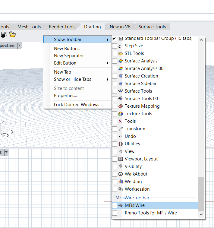
Figure 2: Enabling the MFis Wire or Rhino Tools for MFis Wire toolbar.
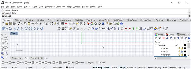
Figure 3: MFis Wire toolbar and Rhino Tools for MFis Wire toolbar docked above the 3D view.
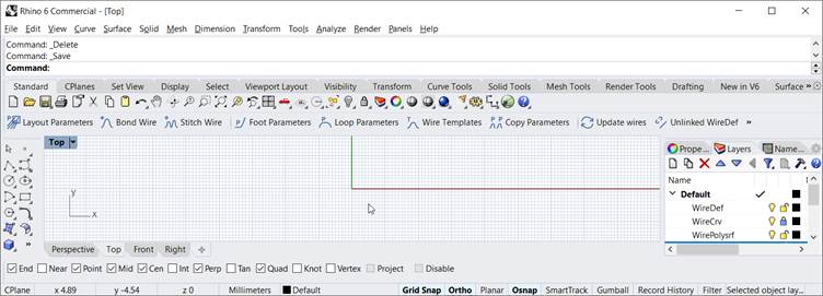
Figure 4: MFis Wire toolbar docked above the 3D view and showing text and icons.
4.1.1 Known Bug
When updating from Rhino 6 to Rhino 7, the MFis Wire toolbar might disappear. If this is the case, uninstall and reinstall the plug-in as described in section 3.
4.2 Text Box Validation in Dialogs
The text boxes in dialogs use validation. If you enter an invalid value, the text will be coloured red. An error message is displayed in the tool tip of the entry box. Hover the mouse over the text box to see the error message. If you click an action button to process the entered values, e. g. the Apply button, the text box entries with validation errors are ignored.
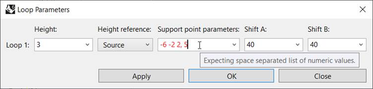
Figure 5: The loop parameters colouring an input field red due to an error (in this case the comma must be removed).
5 MFis Wire Object Handling in Rhino
5.1 MFis Wire Objects
Objects created by MFis Wire are normal Rhino objects that have some additional information attached to it. There are three types of MFis Wire objects (see Figure 6):
· The WireDef object is a Rhino Line or Polyline connecting the bond points of a bond wire. The WireDef object contains all the information of the bond wire.
· The WireCrv object is a Rhino Curve which follows the centre line of the wire.
· The WirePolysrf is a Rhino Polysurface object which represents the 3D wire object.
While the MFis Wire Plug-In is active these MFis Wire objects are treated by the Plug-In. E. g. if a WireDef object is moved, also the corresponding WireCrv and WirePolysrf objects are moved.
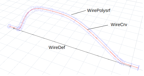
Figure 6 MFis Wire object types.
5.1.1 WireDef Object
The WireDef object is a wire definition object that serves as master object for the WireCrv and WirePolysrf object linked to it. The WireDef object contains all the information of the bond wire. The WireDef object is a polyline with the points describing the bond points.
When you modify the WireDef object, the WireCrv and WirePolysrf objects linked to it are updated. In order to ease modification, after creation of the WireDef object, the curve edit points are turned on. Normally the curve edit points are turned off by pressing the escape key while no object is selected. Because this is easily done without the intention to turn of the edit points, by default MFis Wire will turn-on the edit points of WireDef objects again after the escape key is pressed. However you can still turn-off the edit points of WireDef objects using the Rhino command PointsOff or you can disable automatically turning on the edit points after pressing escape key in the MFis wire document options page (see section 0).
If the WireDef object is modified such that it is not a polyline with the same number of points anymore, the object gets unusable by MFis Wire. The object will be ignored by MFis Wire.
If a WireDef object is modified while MFis Wire is not running or while you have not accepted the MFis Wire end user license, the object gets unusable for MFis Wire, if the modification is other than translation, rotation, mirroring or copying. If this is the case run UpdateWires to detect and revert these changes.
When a WireDef object is copied, a new independent WireDef object is automatically is created. Copying can be done with any Rhino command that creates a copy, also with commands that modify the copy, e. g. using the Mirror command. WireDef objects can also be copied from one document to the other using the clipboard.
If you delete a WireDef object, the linked WireCrv and WirePolysrf objects are deleted also.
5.1.2 WireCrv Object
The WireCrv object is a curve representing the centre line of the bond wire (red object in Figure 6). It is created automatically from the WireDef object.
The WireCrv object is updated automatically if needed, for example when you modify the WireDef object or the LayoutParameters. If you delete the WireCrv object, it is created again the next time the wire is updated.
You can create an independent copy of a WireCrv object. This copy will be a normal rhino object that MFis does not care of. Do this using the UnlinkedWireCrv command.
5.1.3 WirePolysrf Object
The WirePolysrf object behaves exactly the same as a WireCrv object. The object is the 3D representation of the bond wire. You can create an independent copy of it using the UnlinkedWirePolysrf command.
5.1.4 Handling of locked and hidden objects
MFis Wire locks the WireCrv and the WirePolysrf objects by locking its layers (see section 0). The objects itself are not locked.
If the user locks an object, MFis Wire will ignore the lock status and perform all operations as if the object was unlocked. For example if you the wire diameter for a wire layout, also the locked wires will be updated. MFis Wire will maintain the lock status.
MFis wire will also update hidden WireCrv and WirePolysrf objects. Commands that operate on all WireDef objects might include or not include hidden WireDef objects as specified for the command.
5.1.5 Known Bugs
The plug-in does not recognize MFis Wire objects copied from the clipboard into the document before the plug-in is loaded. These are rare cases since the plug-in loads when you first call a MFis Wire command or when you open a document that already contains MFis Wire objects.
Work around: if necessary force MFisWire to start using the UpdateWires command.
5.2 Wire Layouts and Layer Management
MFis Wire organizes the wires in wire layouts. One wire layout consists of three Rhino layers typically named WireDef, WireCrv and WirePolysrf (see Figure 7). The wire layout typically has a parent layer that contains the three named layers.

Figure 7: Layers defined per wire layout.
The WireDef layer is the main layer of the wire layout. If you delete the WireDef layer, you delete the wire layout. MFis Wire will delete all WireCrv and WirePolysrf objects associated with the WireDef objects of deleted WireDef layer at the next execution of a Rhino command. If a WireCrv or WirePolysrf layer is deleted MFis Wire will create new layers when needed.
When a new wire is created or a WireDef object is copied or moved from another wire layout into a layer, MFis Wire tries to associate this layer with a wire layout. It first checks whether this layer is a WireDef, WireCrv layer or WirePolysrf layer of a wire layout or whether a child layer is a WireDef layer of a wire layout. If the layer cannot be associated with a wire layout a new wire layout is created with the layer as parent layer.
After having identified the target wire layout, the WireDef object will be moved into the WireDef layer of the wire layout. WireCrv and WirePolysrf objects are created or updated and moved into the corresponding WireCrv or WirePolysrf layer.
A new wire layout can also be created using the LayoutParameters command (see section 10.3). The current layer will be used as parent layer, the created sub layers inherit the colour from the parent layer. WireCrv and WirePolysrf layers will be created if needed (according to Document Options set, see section 0). To prevent conflicting layer naming, a MFis Wire might add a number to the new layer names. The WireCrv and WirePolysrf layers will be locked after creation. You will not be able to select and modify the WireCrv and WirePolysrf objects in these layers unless you unlock these layers manually. Locking helps working with the WireDef objects while having the WireCrv and WirePolysrf objects still visible.
All layers can be renamed and moved freely. This will not affect the behaviour of MFis Wire.
Recommended work flow to duplicate
a layout:
Create a new layer with the desired layout name. Select all WireDef objects of the
layout to be copied by right clicking the WireDef layer and choosing Select Objects. Copy these objects to the newly created layout
by right clicking the target layer and choosing Copy
Objects to Layer.
5.2.1 Known Bugs
When you copy the whole layer tree of a layout using Duplicate Layers and Objects in the context menu in the Rhino layers tree, the duplicated WireCrv and WirePolysrf layers and objects will not be associated with the duplicated WireDef layer and WireDef objects respectively. As a result MFis Wire will create new layers named WireDef 2 and WireCrv 2 layers as soon as you modify a wire.
Work around 1: after duplicating the layer tree of the layout, delete the duplicated WireDef and WireCrv layers, execute the command UpdateWires.
Work around 2: don’t copy the layer tree, use the recommended work flow for duplicating a layout.
When you delete a WireDef layer containing WireDef objects, the associated WireCrv objects and WirePolysrf objects are marked for deletion but not deleted immediately. The associated objects are deleted after execution of the next Rhino command.
5.3 Undo Redo
All Undo and Redo is managed by Rhino and generally works as expected.
Changes to wire templates cannot be undone or redone.
5.3.1 Known Bugs
When a new wire layout is created and directly afterwards undo and redo is called, the restored layers of the wire layout are not recognized anymore as layers of a wire layout. If the wire layout was created by drawing a wire, the restored wire after undo and redo will cause MFis wire to create another wire layout using the original WireDef layer as parent layer.
Work around: Don’t call undo and redo directly after creating a new wire layout. If you happen to do it anyway, clean up the layers manually.
6 Layout Parameters
The layout parameters are the parameters that apply to all wires within a layout. The layout parameters of the current layout can be edited using the LayoutParameters command. Depending on the cross section type, some parameters might be not applicable. These parameters are greyed out in the dialog as shown in Figure 8.

Figure 8: Layout parameters dialog.
6.1 Bond type
The bond type can either be Wedge bond or Ball bond. In case of Ball bond, the loop at the source bond point starts in up direction. In order to achieve a ribbon bond select Wedge bond and Rectangular cross section.
6.2 Diameter
The diameter of the wire or the ribbon thickness in case of rectangular cross section.
6.3 Penetration
Defines the amount the wire penetrates into the substrate. When set to 0, the wire just touches the substrate. When set to 1, the full diameter of the wire will be within the substrate. The default penetration is 0.25, the wire then penetrates 0.25 * diameter deep into the substrate as shown in Figure 9.
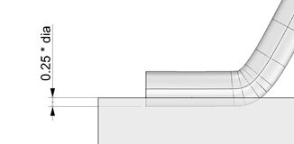
Figure 9: Default penetration is 0.25
6.4 Cross section shape
Can either be Circular, Polygonal or Rectangular.
6.4.1 Known bugs
Wires of rectangular or polygonal shape can have distorted surface shading. The distortion typically appears at the foot and after a wire is modified, e. g. moved. This is expected to be a Rhino display issue and not have any influence on the functionality of MFis Wire.
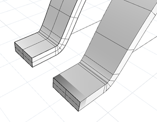
Figure 10: the foot of a new (left) and modified wire (right) of rectangular cross section are shaded differently
6.5 Number of sides
In case of polygonal cross section, this is the number of sides of the polygon. The bottom side of the polygon is always in horizontal orientation.
6.6 Diameter definition
In case of polygonal cross section, this defines how the diameter should be interpreted. If set to Equal area as circle, the size of the polygon is such, that it matches the area of a circle of the specified diameter. Other options are Inner diameter or Outer diameter. With these options the diameter is interpreted as the diameter of the circumscribed or inscribed circle or the polygon.
6.7 Width
In case of rectangular cross section, this specifies the width of the rectangle. The height of the rectangle is defined by the diameter.
7 Foot Parameters
7.1 Support Point Parameters
The WireCrv objects, which represent the centre line of the bond wire, are created by MFis wire using Nurbs curves of degree 2 (read more about Nurbs curves on Wikipedia). A Nurbs curve is defined using a number of support points.
Figure 11 shows the WireCrv for a 10 mm long bond wire created using default settings. The control points are made visible using the PointsOn Rhino command. The WireCrv object is defined by four control points at the source foot (left), three points on the loop support line and again four points at the destination foot (right). The position of each control point on the respective support line is defined by its support point parameter. The default foot support point parameters for wedge bond wires are shown in Table 1.
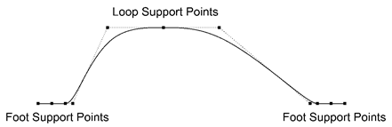
Figure 11: The support points that define a WireCrv object.
|
|
default support point parameters |
|
source foot |
-12 0 6 18 |
|
stitch foot |
-14 -4 0 4 14 |
|
destination foot |
-18 -10 0 13 |
Table 1: Default foot support point parameters for wedge bond wires.
The parameter list must be defined as space separated list of values. The unit of the parameters is 1/10 of the diameter of the wire as illustrated in Figure 12. A parameter value of 0 results in a support point exactly at the position of the defined bond point. Positive parameters result in support points shifted in bond direction. The number of support points can vary, but at least one point per foot must be defined.
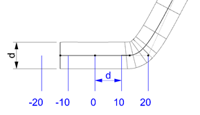
Figure 12: The unit for foot support point parameter definition is 1/10 of wire diameter. The example shows a source foot.
For ball bonds, the support point parameters of the source foot are defined differently. The default support point parameters are 0 5 7. The unit of the parameter is 1/10 of the loop height.

Figure 13: Source foot support points for ball bonds.
7.2 Rotation
The counter clockwise rotation of the foot in degrees.
7.3 Rotation Reference
|
Forward |
The foot rotation reference is the direction to the next foot. |
|
Backward |
The foot rotation reference is the direction from the previous foot. |
|
Bisector Fwd Bwd |
The foot rotation reference is the bisector of the two directions above. |
|
Snap to axis |
The foot rotation reference snaps to the closest axis direction. The rotation reference before snapping is calculated using Forward method for the source bond, Backward method for the destination bond and Bisector Fwd Bwd for stitch bonds. If the rotation reference is a 45° angle, y-direction is preferred over x direction and x direction is preferred over z direction. |
7.4 Foot Parameters Dialog
The Foot Parameters Dialog is obtained by calling the FootParameters command. You will be asked for a selection of WireDef objects if you did not select some before already. The dialog box for modifying the foot parameters of the selected wires is opened.
If a given parameter varies over the selected wires. The content of the entry boxed is “varies”. Also the user can set the content of the entry boxes to “varies”. In that case clicking the “Apply” or “OK” button will not modify the selected parameters.
The selected wires can have varying number of feet. The dialog box displays a number of rows such that it fits the bond wire with the highest number of feet. The parameters of last row always refer to the destination foot, also if a wire is has less feet than displayed rows in the dialog box.

Figure 14: Foot Parameters dialog.
8 Loop Parameters
8.1 Height
The loop height specifies the distance in up direction between the reference point and the highest point of the wire.
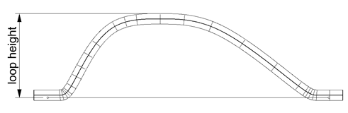
Figure 15: Definition of loop height.
8.2 Height Reference
The height reference can take the values “Source” or “Destination”. According to this value the loop height is interpreted. The reference is either the source bond or the destination bond of the wire.
8.3 Support Points Parameters
As described in section 7.1, the centre line of the bond wire is described using a curve defined by its support points. Typically three loop support points define the loop shape. The three points lie on a loop support line which is located at the defined height of the loop above the reference bond point (see section 8.2). The position of the support points is defined by its support point parameters. The default support point parameters are -6 -2 1, the resulting loop shape is shown in Figure 16. The unit of the loop support point parameters is 1/20 of the horizontal distance between the bond points. For a support point parameter 0, the support point will be in the midpoint between the two bond points. The support point parameters must be specified as a space separated list of numeric values in ascending order.
Examples of other support point parameters are shown in Figure 17 to Figure 19. The number of support points is not limited to 3. With more than 3 points, a loop segment will be fully straight like shown in Figure 19. With less than 3 parameters, the defined wire height will not be reached. At least one support point must be defined.

Figure 16: Definition of loop support point parameters. Wire with default loop support point parameters -6 -2 0.
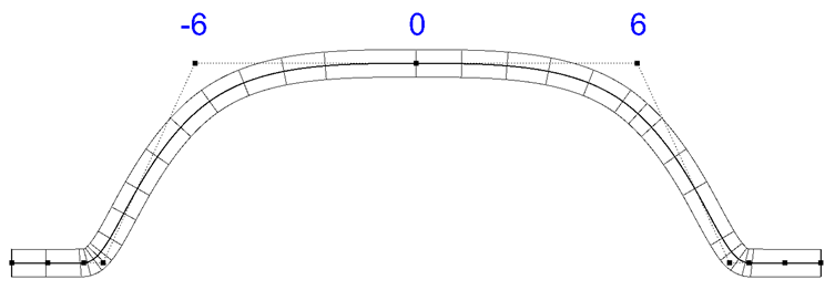
Figure 17: Wire with loop support parameters -6 0 6.

Figure 18: Wire with loop support point parameters -2 0 2.
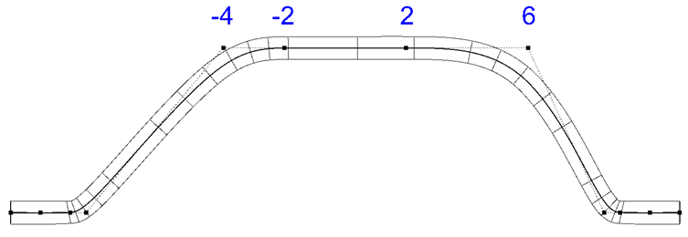
Figure 19: Wire with four loop support points with parameters -4 -2 2 6.
8.4 Shift A, Shift B
If a bond wire foot is rotated, this has impact on the loop shape. The loop support line on which the loop support point parameters are defined is shifted to the side. Figure 20 illustrates how increasing the shift parameters from the default value 40 to the higher value of 80. The unit of the value is 1/10 of the wire diameter. In the example, the wire diameter is 0.375 mm, the default shift parameter of 40 shifts the loop line therefore by 1.5 mm, the value of 80 by 3 mm.
In cases of high shift parameter values in comparison to the loop length, the shift parameters are internally decreased automatically when calculating the lop support line in order to prevent inversed loop directions.
|
top view |
front view |
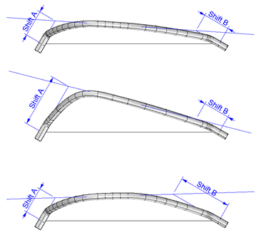

Figure 20: Effect of varying the shift parameters on the loop shape. The front view is the same for all three wires.
8.5 Loop Parameters Dialog
To open the loop parameters dialog, use the command LoopParameters. You will be asked for a selection of WireDef objects if you do not already have WireDef objects preselected.

Figure 21: Loop parameters dialog.
If the parameter of loop varies over the selected bond wire, “varies” is displayed in the text or drop down boxes. If you set a value to “varies”, the parameter will be ignored when clicking the Apply or OK button.
9 Wire Templates
Wire templates contain loop parameters and foot parameters that can be applied to new or existing wires. The templates can be edited using the Wire Templates dialog obtained by calling the command WireTemplates. The wire templates are stored with the document.

Figure 22: Wire Templates dialog
The wire template contains foot parameters for the source, stitch and destination and destination foot. For the source foot, the templates contains the parameters twice, once for the ball bonding variant and once for the wedge bonding variant. For a detailed explanation of the individual parameters see the sections 7.1 and 8.3.
There is always the template Factory Defaults. The Factory Defaults template cannot be edited, however, it can be selected for being used for new wires, you can apply this template to existing wires and you can create a copy of the Factory Defaults by clicking the New button.
If you uncheck Use this template for new wires for a template, the Factory Defaults template will be set as template for new wires.
When clicking the From wire button, you will be asked to pick a WireDef object. The dialog shown Figure 23 appear that lets you choose which parameters to read from the wire and write to the template. The stitch foot parameters are read from the first stitch foot, if any. The loop parameters are read from the first loop.
When clicking the Apply to wires button, you will be asked to pick WireDef objects. A dialog similar to the one shown in Figure 23 appears that lets you choose which parameters you want to apply to the selected wires.

Figure 23: dialog when getting or setting wire parameters
10 MFis Wire Commands
10.1
BondWire 
The commands lets you choose a source bond point and a destination bond point and add a bond wire to the document. The wire will be added to a wire layout that can be associated with the current layer or a new wire layout will be created. The created WireDef object is selected.
10.2
StitchWire 
The commands lets you choose a number of bond points and add a bond wire to the document. The wire will be added to a wire layout that can be associated with the current layer or a new wire layout will be created. The created WireDef object is selected.
10.3 LayoutParameters 
The command opens the wire layout dialog for the wire layout that is associated with the current layer. If no wire layout can be associated with the current layer, a new layout is created. In this case, the current layer becomes the parent layer of the layout. The child layers WireDef, WireCrv and WireDef are created (the latter two only if needed according to the document options, see section 0).
The recommended procedure for creating a new layout is first creating a new layer or select an existing layer. Give this layer a useful name (e. g. Wire Layout 1) and choose a colour. Make this layer the current layer and then call the LayoutParameters command. The result will be as shown in Figure 24.
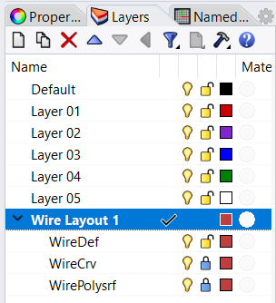
Figure 24: Layers after creating a new wire layout.
10.4
FootParameters 
The command lets you choose a number of WireDef objects, if you don’t already have WireDef objects selected, and then displays the foot parameters dialog. See section 7.4.
10.5
LoopParameters 
The command lets you choose a number of WireDef objects, if you don’t already have WireDef objects selected, and then displays the loop parameters dialog. See section 8.5.
10.6
WireTemplates 
The command opens the wire templates dialog that lets you define and use wire templates.
10.7
CopyParameters 
Using the command CopyParameters, you can copy the loop and foot parameters from one wire to other wires. First select the wire you want to copy from, then select the wires to copy to. The dialog shown in Figure 25 let you choose what parameters to copy. If the wire to copy from has no stitch bond, the stitch box check box is unchecked and disabled. If a wire to copy to has more feet and loops than the wire to copy from, the parameters of the last loop and the last stitch foot are copied to the remaining loops and stitch feet.
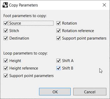
Figure 25: Copy Parameters dialog.
10.8
UpdateWires 
The command UpdateWires updates the WireCrv and WirePolysrf objects of all WireDef objects including hidden and locked WireDefs. Within all unhidden objects it looks for WireDef objects that are externally modified other than translated or rotated and for WireCrv and WirePolysrf that aren’t linked anymore to a WireDef object. If such objects are found the Update Wires dialog shown in Figure 26 is shown for asking you what to do with these objects.

Figure 26: Update Wires dialog
Revert external changes option:
WireDef objects that are externally modified will be reverted back to the state when they were last modified while MFis Wire was running. This makes the objects editable again.
Convert to normal Rhino objects option:
MFis Wire specific data stored with the object is removed. MFis Wire will not recognize the objects anymore. The objects are moved to another layer. The layer the object is moved to is named according to the origin layer of the object while « - unlinked» is added to the layer name. Newly created « - unlinked» layers are not locked, so you can select and modify the converted objects.
10.9
UnlinkedWireDef 
When calling the command UnlinkedWireDef, you will be asked to select WireDef objects. Copies of the selected objects will be converted to normal rhino objects that are in the geometry identical to the WireDef objects but are not recognized by MFis Wire as WireDef objects anymore. The objects will be placed in separate layers. The layer names are derived from the layer name of the layer that contains the original WireDef object by adding « - unlinked» to the name.
10.10
UnlinkedWireCrv 
When calling the command UnlinkedWireCrv, you will be asked to select WireDef objects. For the selected WireDef objects, wire curve objects will be created as normal Rhino objects which are not recognized and treated by MFis Wire. The objects will be placed in separate layers. The layer names are derived from the layer name of the layer that contains the original WireCrv object by adding « - unlinked» to the name. If a new layer has to be created, it will not be locked as the original WireCrv layer typically is.
10.11
UnlinkedWirePolysrf 
When calling the command UnlinkedWirePolysrf, you will be asked to select WireDef objects. For the selected WireDef objects, wire polysurface objects will be created as normal Rhino objects which are not recognized and treated by MFis Wire. The objects will be placed in separate layers. The layer names are derived from the layer name of the layer that contains the original WirePolysrf object by adding « - unlinked» to the name. If a new layer has to be created, it will not be locked as the original WirePolysrf layer typically is.
10.12
MFisWireLicense 
The command MFisWireLicense brings up a menu dialog that lets you view license information and manage the licenses. See section 12 for details.
10.13 LoadMFisWirePlugIn
The command LoadMFisWirePlugIn command forces the MFisWire plug-in to load. This command is used by the plug-in internally and has no toolbar icon. In rare cases where the you need to force the plug-in to load, e. g. before copying MFis Wire objects into a new Rhino document, you can use this command or as well any other MFis Wire command like UpdateWires to force MFis Wire to load.
10.14 Rhino Tools for MFis Wire
The commands described in the following table are ordinary Rhino commands that are useful in the context of modelling bond wire layouts. These commands are provided in the Rhino Tools for MFis Wire tool bar.
|
|
Change the view to wire frame. |
|
|
Change the view to shaded mode. |
|
|
|
|
|
|
|
|
Selects open curves, e. g. WireDef objects. |
|
|
|
|
|
Sets the origin of the construction plane. |
|
|
Allows to define a point which is in the center between two other points. |
|
|
Draws a line |
|
|
Duplicates the border of a face of a solid object. The resulting object is a curve. |
|
|
Lets you select the edges of solids which should be duplicated. The resulting objects are curves. |
|
|
Creates an offset curve to another curve. Use this for example to define the area where it is safe to bond with a defined safety margin to the bond pad border. |
|
|
Connects lines by extending or trimming the input objects. |
|
|
Creates copies of objects. You can for example copy WireDef objects. WireCrv and WirePolysrf objects will be created automatically for the copied WireDef objects. |
|
|
Creates copies of objects in a linear arrangement. Apply it to a WireDef object to create a row of bond wires with a defined pitch. |
|
|
Create mirrored objects. Mirror bond wires by mirroring the WireDef objects. |
|
|
Scales objects in one dimension. Use this to change the pitch of a row of bond points. |
|
|
Projects objects to the construction plane. Useful to create 2D documentation of bond wire layouts. First create the unlinked WireDef or WireCrv objects you want to have in your 2D drawing, then projects the objects to the construction plane. |
|
|
Moves an object by 0.1 mm in the indicated direction. You can also move individual bond points. The distance to move is adjustable by editing the button action. |
|
|
Set coordinates of objects. Use this to align bond points with other objects or to enter coordinates. For example apply this command to a bond point, select to set only x coordinate and enter the coordinate or select another bond point to align with. Choose the option Align to CPlane if to define coordinates relative to your construction plane defined. |
|
|
Flips the direction of curves. Apply it to WireDef objects to flip the bond direction. Right clicking the button will visualize the direction of curves. |
|
|
|
|
|
Prints the coordinates of a point. |
|
|
Analyze the curvature of surfaces. Use this to detect issues with knit bond wires. Unlock the WirePolysrf plane, select the WirePolysrf objects and click this button. Select min radius and click Max Range. If the lower value is close to 0 you might have self-intersection wire objects which cause troubles in finite element or other simulation software. |
|
|
Create a 2D drawing of 3D objects. Select CPlane as projection. For documenting a bond layout in 2D, you typically use this command to create a 2D drawing of the original part without bond wires. The bond wires you add later by unlinking WireDef or WireCrv objects and projecting them using Project to CPlane. |
|
|
Creates points at the start of curve objects. Applied to WireDef objects this will create points for the source bond points of the wires. Right click to mark curve ends / destination bond points. |
|
|
Creates points at all control point locations of objects. Apply this to WireDef objects to create points for all bond locations, including stitch bonds. |
|
|
Add coordinates to document a 2D bond wire layout drawing. Set the base point to the reference point used by your wire bonder. For that, click the Basepoint option in the command line. Change the style by opening from the menue Dimensions à Annotation Style. Change the size by changing Model space scale. Convert mm to µm by specifying a Length factor of 1000. Choose the number of digits under Linear resolution. |
11
Document Options 
MFis wire has a document options page in
the rhino document properties dialog. You find the document properties dialog
via the menu Tools à Options.
In the tree view find the entry for MFis Wire. Clicking the Document Options button ![]() in the MFis Wire
Toolbar will get you directly there.
in the MFis Wire
Toolbar will get you directly there.

Figure 27: MFis Wire document options page.
|
Option |
Description |
|
Up direction |
In your model the up direction might not be in z direction. You can change this here to the +/-X, +/-Y, +/-Z. |
|
Draw wire curves |
You can enable or disable drawing of WireCrv objects. Disabling will delete all WireCrv objects. Enabling will create them again. |
|
Draw wire polysurfaces |
You can enable or disable drawing of WirePolysrf objects. Disabling will delete all WirePolysrf objects. Enabling will create them again. Disabling can increase comfort during layout creation due to speed increase and not having the WirePolysrf objects covering the WireDef objects. |
|
Keep edit points of WireDef objects turned on |
If selected the edit points of WireDef objects are turned-on after pressing the escape key (see section 5.1.1). |
Table 2: MFis Wire document options.
When navigating to another options page the changes will be applied. The changes can still be reverted by clicking Cancel. Clicking OK will apply the changes immediately and close the dialog.
12 License
In order to use MFis Wire you must have accepted the license agreement and have a valid license. A valid license can
be a purchased license, an evaluation license for which you obtained a license
key from MFis or the 15 days trial license you can enable once for each device.
When you first run a MFis Wire command, dialogs are shown to let you accept the
license agreement and activate the device with a license. You can also find the
license dialogs and other license management options using the MFisWireLicense ![]() command which
brings up the menu shown in Figure 28.
command which
brings up the menu shown in Figure 28.
After expiration, MFis Wire will not execute any commands anymore and not update modified MFis Wire objects.
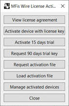
Figure 28: dialog showing License information and management options.
12.1 Managing activated devices
Using the button Manage activated devices in the dialog shown in Figure 28, you can see which devices are activated for the license key you are using. In the device list, the device you are using is selected by default and marked with (this device) after the hostname. Each device is listed with its unique device code and the activation date.
If MFis Wire is not used anymore on one of the devices you can deactivate that device. This allows a another device to activate instead. However the number of deactivations is limited per license key. This number will be refilled when renewing the license subscription.
If you deactivate the device you are using, the local license information will be deleted and you will not be able to use MFis Wire unless you again activate the device using a valid licence key. If you deactivate another device, that other device still has the license information stored locally and will activate again, the next time MFis Wire is used on that device. It is therefore recommended, to deactivate other devices only when knowing these devices are not anymore in use or MFis Wire is successfully uninstalled from these devices or another MFis Wire License is used on these devices.
12.2 Offline use
The validity of the license is checked online once per Rhino session before the first activity of MFis Wire. If you are offline you can continue using MFis Wire up to 30 days from the last online license verification.
If for some reason you cannot connect to
the license server hosted by Cryptolens, you can request an offline activation
file by e-mailing to wire@mfis.ch. Use the template
shown when clicking the License ![]() button and selecting Request Activation File in the menu. The template
contains the needed information like hostname
and device code. Don’t forget to fill your
license key.
button and selecting Request Activation File in the menu. The template
contains the needed information like hostname
and device code. Don’t forget to fill your
license key.
When you received an activation file from MFis, you can load it by clicking clicking the License ![]() button and selecting Load activation file. Typically you can use a license
offline for 30 days. If within your company you generelly cannot connect to the
Cryptolens license server, you might agree on a longer offline usage time with
MFis.
button and selecting Load activation file. Typically you can use a license
offline for 30 days. If within your company you generelly cannot connect to the
Cryptolens license server, you might agree on a longer offline usage time with
MFis.