
MFis Releases Unit Aware Calculator for Engineering
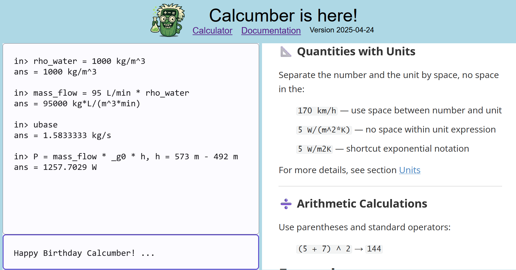
Unit aware calculation makes it easy!
Calcumber is a web app and can be used without download on desktop and phone. Start now at calcumber.app! Read the Calcumber documentation to learn more.
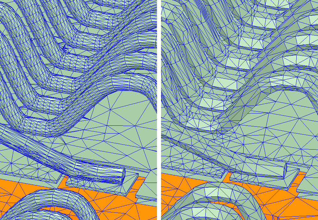
Creating Wire Bond Layouts in Inventor
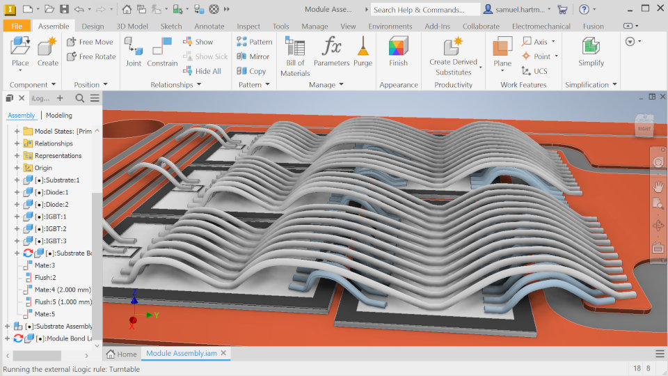
With MFis Wire, bond pads and helper lines sketched in Inventor serve as references for fast, precise bond layout creation. The final geometry updates automatically in Inventor, and all data is stored within the file – ensuring seamless integration with document management systems.
On our YouTube channel, you find a demo video in german.
Contact us for more information, a demo.
Our Engineering Services
We have a strong background in engineering power electronics components, for which high currents, heat, magnetic fields and mechanical stress must be managed at the same time. This multi-disciplinary view enables valuable product analysis and optimization. By transfering tools and methods developed by MFis, we empower your engineers to devolop high performing products.
Finit Element Analysis
fluid flow | heat transfer | mechanical | electro-dynamic
Power Module Design
geometry modelling | virtual prototyping
Data Analysis
scripting | model fitting
Life Time Modelling
physics based | mission profile analysis